Wednesday, 5 June 2019

Refit Part 2 - Repairs, Reassembly and Re-launching

All 'Enfys' keel bolts came out relatively easily, bar two centre ones that refused to budge. These were seriously wasted and either bent when we tried to drive or the punch slipped off and got jammed. A magnetic base drill was set up over them and we laboriously chewed away at the tops of these until we could get a drive onto the stump and push out the remains of one of the bolts. The other one we heated from below and managed to free it. On both these bolts the holes through the ballast keel were not true and the bolts had been bent when originally installed.

The original imperial 5/8" and 3/4" bolts were replaced with M16 and M20 and the holes were run through with long-reach drills to open them out.

New zinc-plated high-tensile hex head bolts were procured and were installed with a cotton grommet and bitumastic sealant around the outboard head and as they were driven up liquid tar paint was poured in from above to completely flood the hole and encapsulate the washers and nuts.


The pair of bolts aft of the bulkhead and under the engine were fitted longer and set onto dense plastic blocks about 25mm high in an attempt to keep them above the bilge water puddle.
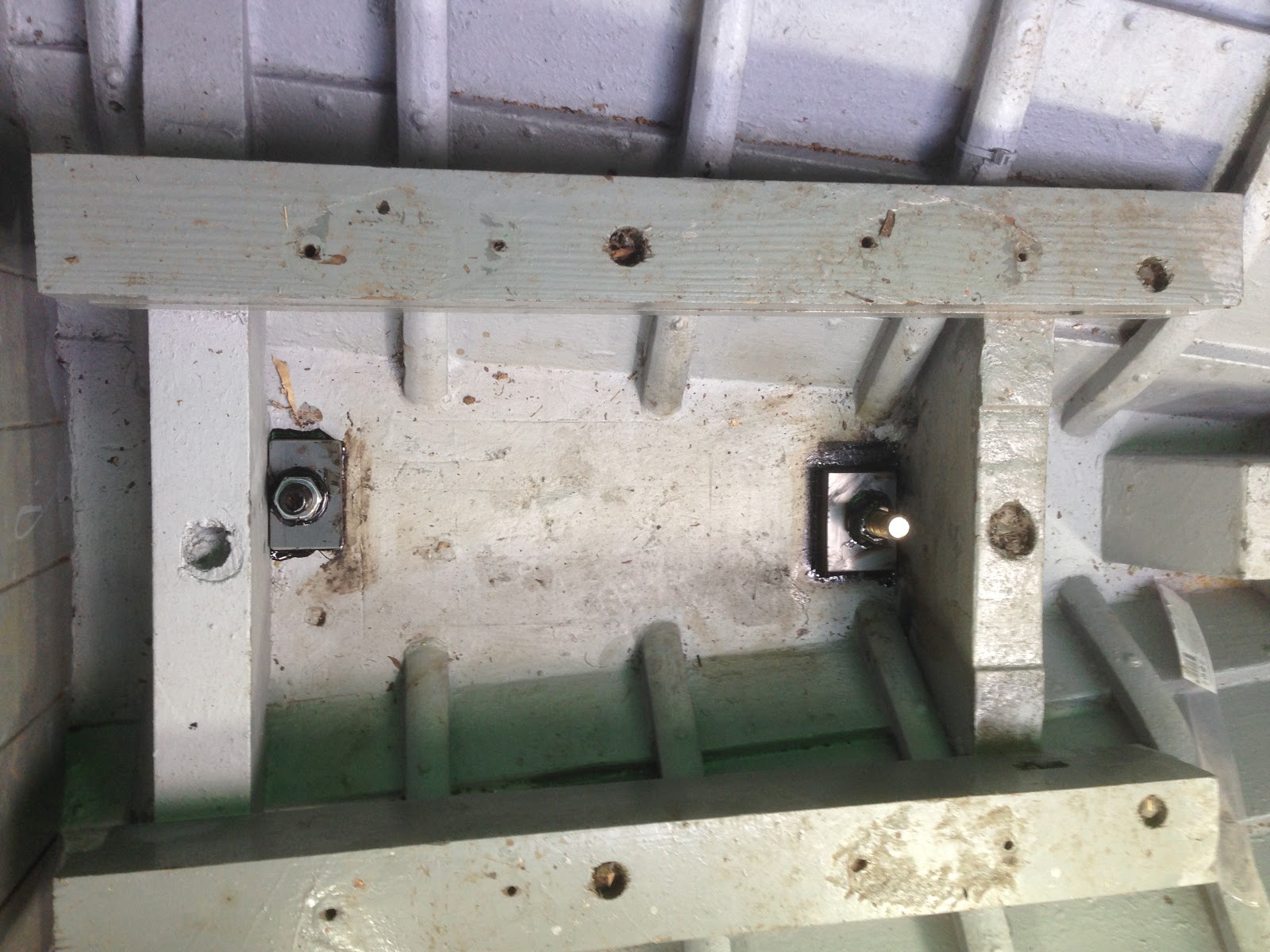
On the underside of the ballast keel the bolt head recesses were filled with mortar with a waterproofer added.

The exposed faces of the lower part of the centreplate case that is only accessible from under the boat were found to be a bit worn and ragged from the effects of immersion, lack of paint and the chafe from the centreplate. A simple scraper and wire brush on long handle was used to clean the barnacles and loose stuff off and the bare timber was treated with penetrating epoxy followed by a couple of generous coats of underwater primer. A small paint roller on a long handle reached into all the corners.


The centrecase under bolts were plugged-over and the upper part of the centreplate case reassembled with newly-made sides in iroko. Sikaflex was used for all faying joints and it was here that I discovered a problem: the Sika has a problem with the underwater primer and seems to 'melt' it so that the Sika does not stick.


The centreplate case was finished off with new sill battens to help support the lower joints and cappings fore and aft.  A new capping piece was fastened down onto the lower casing with bitumastic sealing strip. Epoxy sealer was used on all faces that were potentially going to get wet or to be covered in sealant. The casing was varnished and the cabin furniture re-fitted.


Moving aft the ragged stern post was tackled.  The degradation of the timber was limited to the area surrounding the stern tube and the inboard section before the rabbet, only.  The upper part of the stern knee was chiselled away leaving the bolts in place (which we couldn't shift but were in OK condition). The stern tube was pulled out and the plank hood-end fastenings in way of the tube were drawn out.

The damaged area was built up with thickened epoxy around the tube and new timber was cut and morticed to fit in. The existing bolts were supplemented by coachscrews and the whole lot glued firmly into place. New fastenings were driven making sure that they did not make contact with the tube. The stern tube was wrapped in PVC tape to isolate it from the surrounding timber and the inboard and outboard bearings refitted.


The bilges were primed and painted again.
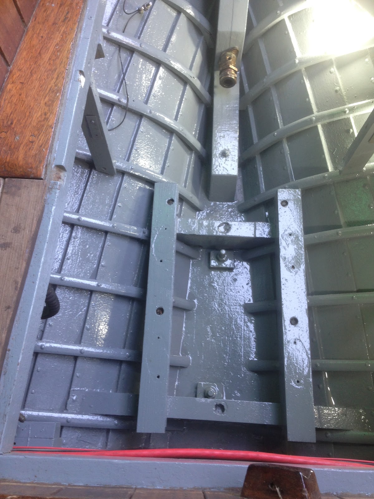

'Enfys' centreplate had been away having the pivot bolt hole closed up and re-drilled, blasted and hot-dip galvanised. It was wedged upright on a modified pallet and the yacht was lifted over it, jacked into place, pivot bolt fitted and wire connected and wound onto the winch.


The engine was serviced, filters changed, filled with gear and engine oil and was slung back into place. It was lined up with the re-installed propeller shaft and the exhaust, fuel tank, cooling pipes, control cables and wiring harness re-connected. A splash of diesel in the tank, bled and she was running!


Finally we took down the winter cover and cleared the boat of tools and surplus materials ready for loading. In between times I had de-rusted the bilge keels and primed them and applied two coats of antifoul.

'Enfys' was loaded back onto the truck and was taken back to Saundersfoot where she was unloaded direct  to the sand next to the slipway whilst the tide was out. Her mast was re-stepped and when at last the tide returned she finally floated.


Thank you for reading; the 2019 sailing season starts here for 'Enfys'...


Tuesday, 12 March 2019

Winter refit. Part 1 - Dismantling and keel-bolt removal

'Enfys' needs some fairly major maintenance and this has been in the planning for about a year. She had a busy 2018 sailing season with about twenty five separate trips and short voyages but with concerns about the condition of her sterntube we decided to carry out work over the winter 2018/2019.
She was brought by road to a yard in Pembroke Dock after mast was unstopped and all heavy and loose gear was removed.
Loaded up for short journey to Pembroke Dock

Sheeted-up to keep the weather out whilst work is carried out

Chocked up and sheeted-over the first job was to unbolt and lift out her engine and associated gear including fuel tank.  The inboard nuts of the two aftermost centreline ballast keel bolts are under the engine.
Engine out to give access for the work to come

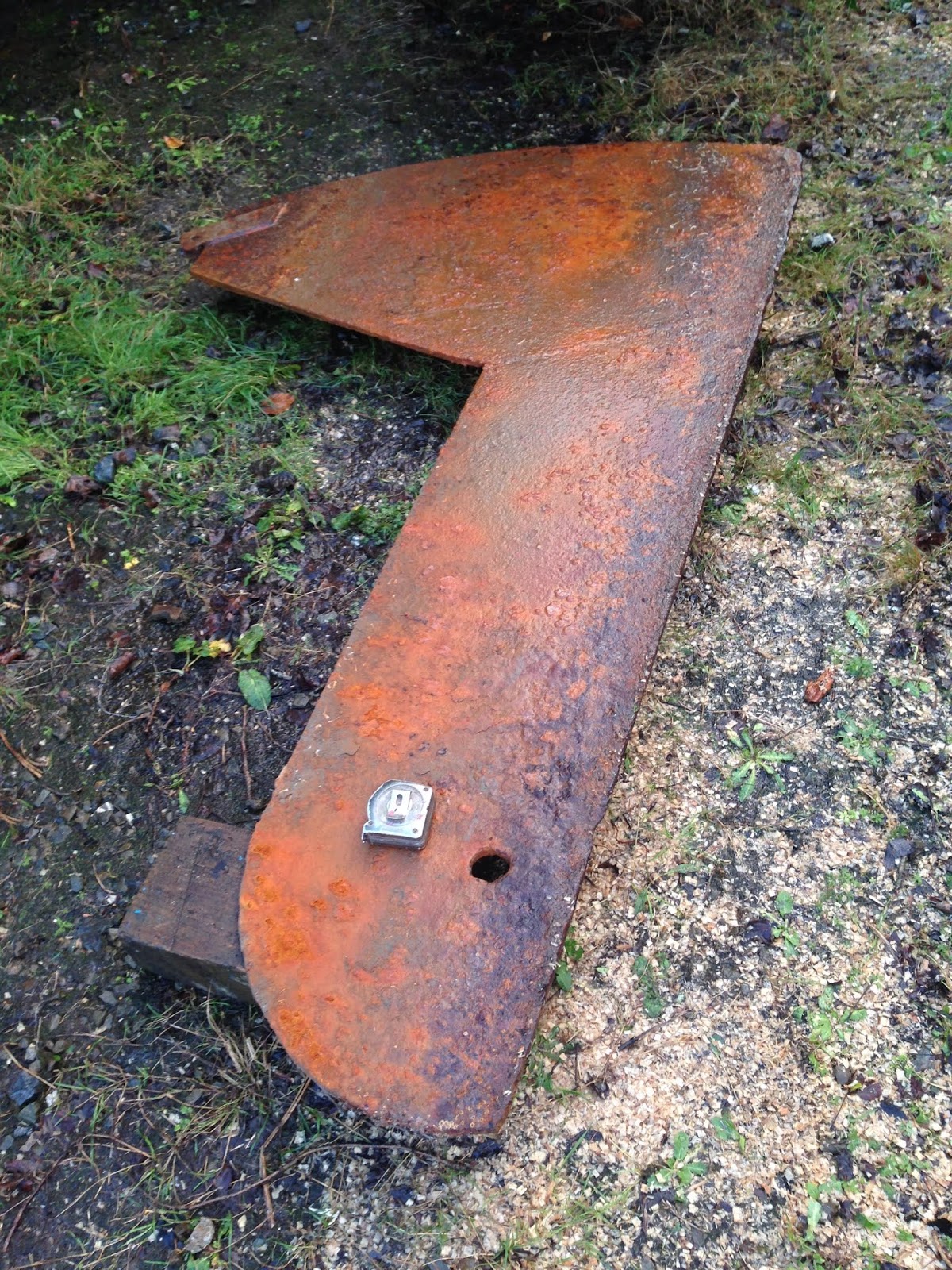
The centreboard lifting wire was disconnected and pivot bolt removed - here it is after just four seasons' use showing the wasting caused by the fretting and movement of the 'plate in use.  This is an M24 bolt.
Centreplate pivot bolt - 50% gone after four seasons' use

The yacht was lifted off her centreplate to extract it and then set down on blocks high enough to enable the keel bolts to be driven out.
Finesse centreplate - this has been dispatched to be repaired and re-galvanised

Raised up on blocks

The heads of the nuts of the after two centreline bolts had almost completely dissolved away and their remains were chiselled away and the bolts driven out after the mortar encasing the heads in the ballast keel was broken out. Also removed were the first two forward of the centreboard slot. Their nuts were OK as they are rarely wet compared with the aft ones which are normally submerged in bilge water.
There is one further bolt right at the forward end of the ballast keel but its nut is hidden under the heads and it has been left for now.
All the bolts were intact and the forward ones were still dripping with tar from when they were first installed. The main area of wastage of these was in way of the main timber keel.  These centreline bolts are 3/4" BSW and range in length from 250mm to 290mm. (Going metric for the replacements!)
Forward keel bolts driven out - still covered in their original tar.

The next stage was to expose the inboard ends of the keel bolts alongside the centreboard case.  There are four of these each side but they are underneath the centreplate case upper part and capping so we had no option but to remove it all.  This casing needs attention though as there have been 'rusty weeps' seeping in through the lower part for years and this was only going to get worse with time.

A bit of dismantling of the galley unit and the companionway step was required to free the centreplate case sides and they were carefully unfastened. A replacement forward capping had been Sikaflexed and screwed to the forward face at sometime in an attempt to stem the seepage and the Sika sticks so well I had no choice but to chisel the capping to bits to get it off.
'Plate case forward capping had to be chiselled off

Most of the screws holding the cabin sole capping had to be drilled or broke off but eventually it was free to prise off.
Lower capping - evidence of minor weeping through the sealant

After removing some battens that had been added to the foot of the case and rows of screws and the copper through-fastenings the case sides were freed and removed. The original glue lines had long failed and the step joints were full of mud and crumbling sealant - no wonder she was leaking.
Centreplate case - starboard side. Circular scour is from lifting wire attachment point.

Plugs over the ballast keel bolts were identified and drilled and picked out. We had to take care to identify the ballast bolts as there are others between them which only fasten the centreboard case to the hog/keel and these were not to be disturbed.

The nuts of these bolts were drilled/chiselled away and all but two of these were able to be driven out but put up more of a fight than the centre bolts as they are much longer; up to 420mm. They are (or were when new) 5/8" diameter.
Nuts under the plugs were all badly corroded.

Two of them refused to give despite a serious beating; one is so wasted it just bent, the other moved a bit but is now solid. We plan to come back to this with a drilling machine to set up over these.
Two very stubborn bolts - resisting a serious beating

Now that there is nothing much holding the ballast keel on we put a temporary length of M12 threaded rod through two of the holes till the new bolts can be fitted.
Temporary studding installed and nutted-up


Saturday, 17 June 2017

Propulsion Machinery - Final mechanical post for now, I promise

This will be the last of the posts I have done about Enfys' machinery - until something else goes rusty or falls off! 


I had to get the engine up to replace a very rusty sump-oil-drain tube and whilst the motor was up out of the bilge I tacked a few other jobs. Having no facilities or need to remove the engine completely from the boat I devised a pair of 'A' frames that stood on the side decks with a strongback between them, over the engine. From this I slung a basic chain hoist with a 500kg capacity (the Beta 20 has a stated weight of 105kg). After disconnecting the engine's pipes, cables and wires and spending a whole afternoon unbolting the rusty clamp coupling and getting the mounting screws out the engine was ready to lift.
The engine was lifted up and turned through 90degrees and placed on blocks that spanned the cockpit floor frames.
Lifting engine


Engine now reasonably accessible
The sump oil was drained and the after a bit of a struggle the rusty elbow and pipe was persuaded to part company with the sump.  New parts were obtained from Beta marine and elsewhere to renew these and also the flexible engine mounts.
Now, I have to say that in my opinion, none of these parts is really suitable for use in a damp salty marine environment; the drain hose is a standard industrial hydraulic hose and the crimped ferrule was just crumbling. Three of the four flexible mounts were totally 'minty'. I found that they were of Italian manufacture and are most commonly fitted to air compressors; made of pressed mild steel and cad plated. To try and prolong the life of the replacements I painted them thoroughly with zinc-rich primer and a few coats of machine enamel.
Rotten sump oil drain connection

Beta engine mounts disintegrating in the marine environment
The whole lot of rusty engine parts were cleaned, treated and painted in some 'Carmine Red' enamel to match the supplier's original spec before being reassembled.

New engine mounted loosely fitted
Whilst the engine was accessible I fitted the Beta-supplied (and very expensive) 'upgrade' of the poly-vee auxiliary belt and pulleys to rid her of the curse of the 'black-dust' and tri-annual re-tensioning of the original 'V' belt. I stripped the alternator again to clean the belt dust from its innards.
Front of motor caked in belt dust - a well-know problem with these early Beta engines

New parts obtained and ready for fitting

Poly-vee kit fitted. A chunk had to be ground off the raw-water pump to let the belt pass.
Whilst the engine was out the bilges were cleaned and painted and the prop shaft was withdrawn to enable replacement of the outboard 'cutless' bearing. The propeller shaft was found to be worn and we were concerned at how badly the propeller had been corroding.
Bilges cleaned...
....and painted.
 
Badly pitted prop, and worn shaft
The 'cutless' bearing was chopped up and pulled out and the housing polished inside with emery on my electric drill. A new sleeve was pressed in as shown...
Method of getting the old 'cutless' out
Winding in a new bearing sleeve

New 'cutless' in place
A new shaft and propeller had been ordered and reeling from the cost I was determined to find out what was wrong with the existing galvanic (cathodic) protection (or lack of it!).
Enfys has a pair of zinc anodes bolted back-to-back through her sternpost that appeared to be connected to the outboard bearing housing. Inboard there was a wire connected between the stuffing box and engine's gearbox.
I made some continuity checks and found that although there was a circuit between the anodes and outer bearing there was no circuit through the stern-tube - it was open circuit, which was quite a surprise! This fact, coupled with the fact that the cable between stuffer and engine was also O/C and that there is an insulating flexible member in the propeller shaft coupling meant that the prop had probably been fizzing away merrily.
What I did to mitigate this was to fit a 'new' anode to the hull with through-hull studs (more holes in the planking.. arrgggh!) which was connected to the stuffing box and engine by new cables. At the prop shaft coupling a stiff copper wire bridges the flexible member. Now, checking continuity the propeller and shaft are all bonded to the anode.
Something odd - sterntube is corroding inside shaft log/sternpost - no continuity to the outboard end, too.
New zinc 'pear' anode fitted to hull

Connecting wires fitted to studs - backing pads will be needed at a later date.

Cable clamped to stuffer with a jubilee clip

Bonding wire connected to gearbox - flexi coupling was also bridged.
Engine back in place, lined-up and coupled
Engine back in place
 The lifting frame was rebuilt and the engine lowered back into place and carefully re-aligned with the shaft coupling.
Another job that I did whilst the shaft was out was to renew the stuffing box packing. A horrible fiddly job that required kneeling in the bilges - but I'm glad I've done it as the annoying drip from the gland has now gone!

The 'plumbing' and wiring was all re-connected, fuel tank refitted and filled, fuel pumped and system bled, batteries switched on, water hose laid on and she started and runs!